Quantum Broadcast Mixer
So, a client of mine asked me to look at a channel on his Quantum Audio Labs mixer. He wanted to add the direct out option to the channel strip. The board layout already had the space for it. Umm, okay. He had full schematics and board layout info. Excellent!
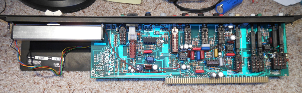
Up until this, in my electronics history, I had not heard of this manufacturer. But the internet yielded a plethora of info all indicating how great this manufacture’s products sounded. Quantum, it turned out, made mixers for the radio broadcast industry and eventually the recording industry as well, although the meat and potatoes was broadcast. And as happens with company’s is long out of business.
After determining the parts list and cost, even if it didn’t work, not a great deal of money wasted, parts were ordered and the board populated. A couple of wiring points added and the commensurate output wire with XLR was done. Cool! As I did not have the capability to test out the channel I gave back to the customer who, in a few days, said it worked perfect. A much better sound and lower noise floor than going thru the mixer buss.
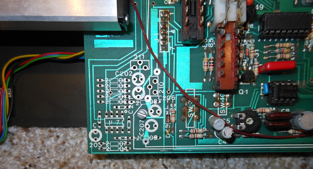

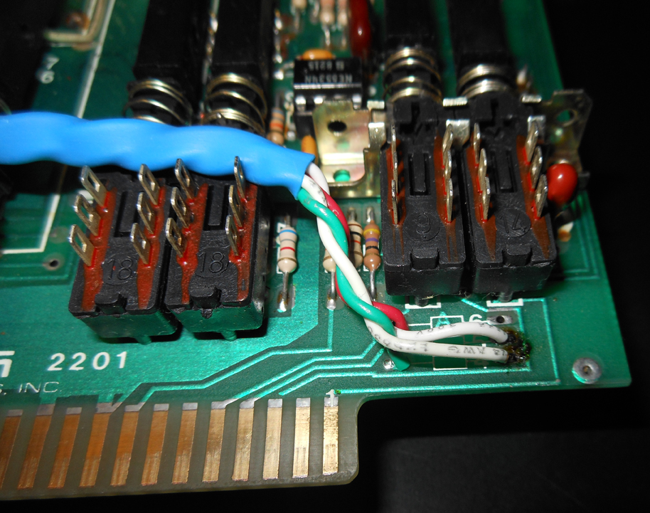
Okay, that project done! Oops! He wants a second channel done and can I add a pad for the mic input that is switchable. Another umm… okay. After studying the schematic and conferring with the client, who is pretty knowledgeable about this mixer, it seamed straight forward. Just take an existing switch and use it to drop in and out a resistor pad to knock down the signal feeding the input transformer. “no problem”! There again off to the internet to find out how other designers dealt with mic pad’s. And in little time had an example on how to achieve the circuit.
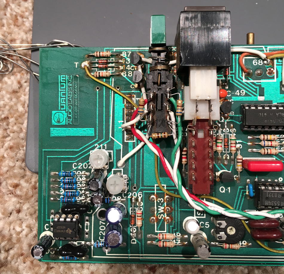
Turned out to be pretty simple, as long as you have the right type of switch. Lucky for the client the switch that was available on the channel was exactly the type needed. Now, to remove said switch and cut traces on the board so as to not interfere with other process’s in the channel circuits. This switch is no longer used as it was to activate a “cart” system in a radio studio. It started a cartridge playback unit which was used to play commercials and the DJ would activate that at the appropriate time. Suffice it to say that the majority of radio stations haven’t used cart players in many years. It’s all computer based now.
This client was so happy with the added direct out option and pad switch, he wants four more channels done. GREAT!
Late 30’s National/Dobro amp
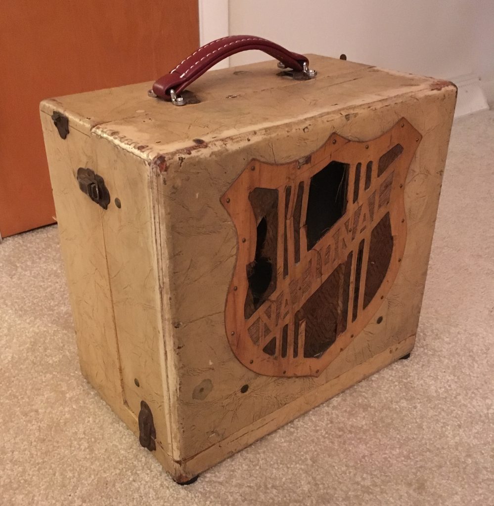
I was presented a old National amplifier by a client that had purchased it not working and wanted to get it up and going again. He thought it may be a model B version.
Upon inspection the main fuse was blown and there was a resistor that literally had exploded.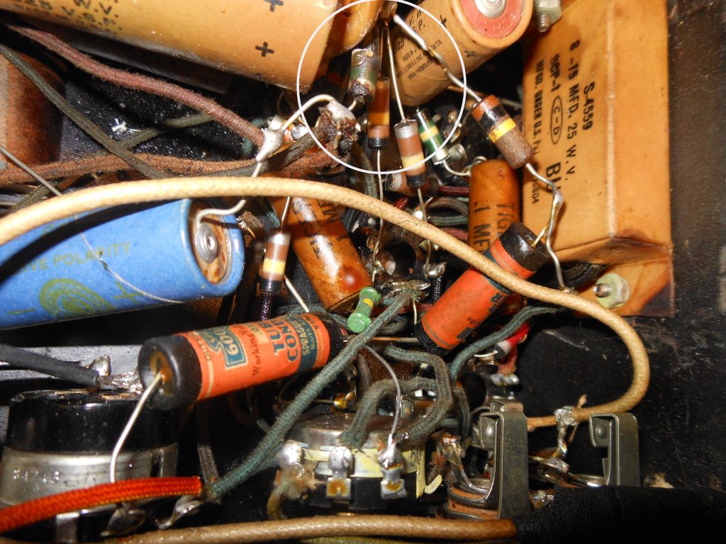
So, first up, what is it? After digging around the internet I discovered that this was actually a Model 13a-15. Made between 1937-38. Talk about ancient.
Finding out that it is a 13a-15 and comparing to what I had, I discovered that this unit was modified as well. Working on old products is a bit like detective work. Finding what it is and has there been any work done or added on to it. This particular model had lots of bits added to the circuits.
Whenever you dig into a piece that does not work you just need to start from the beginning. Why did the fuse blow? Why did the resistor explode?
> Is the power transformer good?
After disconnecting the main B+ from the rest of the circuit I slowly powered up the PT using a variac (variable ac power supply). No current draw. Excellent!
The PT is good.
> Is the rectifier tube good?
Tested the tube on a Hickok and all was good. Installed back into the circuit and powered up again using the variac. All was well.
> On to the rest of the power supply.
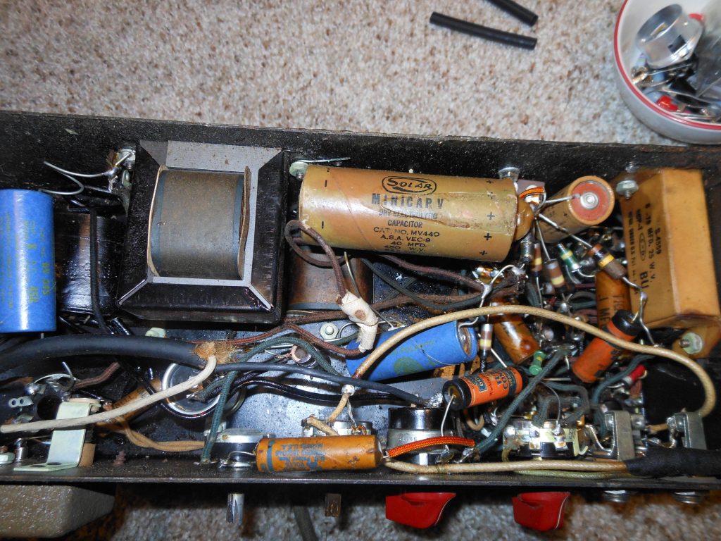
The filter caps looked old. Tested them and found all were defective. Not surprising as electrolytic caps do not last forever. Before I order replacements I needed to look at the rest of the amp including the exploded resistor.
One of the problems with that was, back at that time in electronics history, there was very little standards in resistor marking. More detective work.
If you look at the picture above you will notice that the resistors use a colored body with different bands of color. Not a whole lot on the net about these old markings. Dig dig and dig. I also metered the good resistors and coupled with the schematic and net info, I figured out the code.
> Tested more capacitors, and found defective ones.
> Tested the remaining tubes with the Hickok. All indicated good, no shorts.
> Traced out the mods and compared with the original schematic. Interesting! Just some added volume and a tone control. Cool, will leave as is.
> Ordered necessary parts.
Kind of a mess. I am continually surprised at how some techs do their work. This was pretty hack!
So the resistor that had failed was a 5K ohm that fed the pre-amp and PI (phase inverter) circuit. That large brown cap as well as the blue and small brown cap were all defective. BTW that large cap was an add-on. Not part of the original circuit. Big question? Did the resistor fail causing the cap to go or did the cap fail causing the resistor to go.
So while waiting for the parts to show up I replaced the power cord with a 3 pin ground version and re-wired the ac power in. Safety first!
My thought moving forward is to remove parts that I know were not original to the schematic, rebuild the amp to original specs and take a listen.
Also, the speaker part of the cabinet was falling apart. So off to see my good friend Kris who is a much better wood worker than I, to have him repair the cab. As you can see in the top photo it turned out great! I also added a replacement handle as after 70 years the original one was long gone.
Parts came in and were put in the proper locations. Powered up! Got sound and no unusual current draw. But a nice level of hum. Much more than there should be. Working on tracking down the hum I found 2 of the 6N7 pre-amp tubes to be micro-phonic and found some NOS ones on eBay.
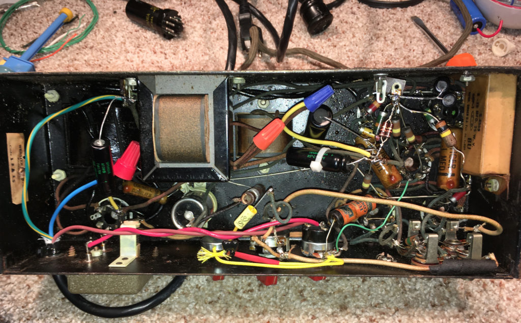
After several value changes and additions to the filter caps with no change in hum level, I studied the schematic closer and noticed that it indicated that the B+ going to the OT (output transformer) was connected on the input side of the choke. As a test, I wired it to the output side of the choke and the hum decreased at least 50% if not more. Cool! Much more acceptable.
I put the amp back together, took some pics and gave back to the client. His first impressions were great! He really liked the sound. After more playing he changed out the 6L6’s and found the amp to really come alive. The old ones were the RCA metal variety.
A week later the client indicated that he was a bit un-thrilled with the way the volume and tone controls worked as they took away good tone when adjusted under normal operations. Volume and tone controls should not dramatically alter the basic tone when being adjusted. So a slight re-design of the modded tone circuit and replacement of the main volume control was in order. Not wanting to really change the basic sound of this amp I looked at the various tone circuits that were used at that time in history. I settled on a tone circuit from a Gibson unit of that vintage.
So now, all is good and at the end of the day tone rules the guitar world.

New Fender Deluxe build, part 2
We are well underway on the Deluxe build. Bill is doing a pretty good job.
He started out populating the main circuit board then moving on to the chassis installing the transformers and pots.

Sorry for my messy workbench!!

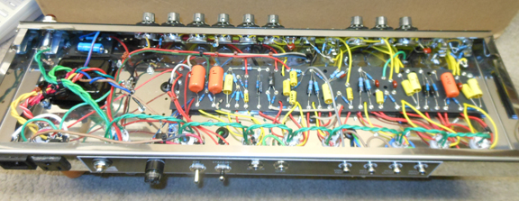
Below, the main board laying in the chassis. Starting to look good.

A look from the back of the chassis towards the front.

New Fender Deluxe build
New Fender Deluxe Build (The beginning)
I teach electronics for audio engineers at a local tech school, Milwaukee Area Technical College in Milwaukee Wisconsin.
One of my students after building a auto wah pedal wanted to kow if I thought he was capable of building a guitar amp.
Of course! I replied. What do you want to build? He replied “not sure”.
Ok, lets have you play through some different types of amps and see what you like.
He started off by playing thru his Fender Blues Deluxe, circa mid 90’s. “very uninspiring”
We then moved on to a hand built 60’s style Tweed Bassman. “much better”
Tried out a ’59 style Prineton. “nice but not quite what he’s looking for”
Moving on he plugged into a Dumble style that I’ve been working on. “OMG, what a sound” (more on this build coming)
A few days later he played on my buddys original 64-65 Fender Pro. “he really liked that blackface sound”
So, after much discussion, it was decided that he would build a Fender Deluxe Reverb based on the ’65 AB763 circuit minus the Tremolo but adding
a Presence and Master Volume control. Also, using a Dumble style circuit for the Normal channel along with a 15″ speaker.
Stay tuned!!! Parts are on order.
Sony MXP-3036 Re-lamping Project
Last summer (July, 2016) I wired in a pre-owned Sony analog mixer for Howl Street Studios.
At that time, Shane the owner/engineer, queried me as to how might I replace the non working lamps in all the meters in the meter bridge.
After a bit of research I found that although the lamps were still available they did not last very long and it was suggested that using LED’s were the way to go.
Okay, interesting. But not now Shane said.
Fast forward to March of 2017 and Howl Street moved to a new location. After the re-wire and getting all audio flowing good again, Shane brought up the subject again. This time he was “ready” to make that happen. How much? he asked.
I answered, “I really don’t know”. And that sent me on a quest to figure out how and what it would take to re-wire/mod 36 channel meters plus 4 master meters with new lighting.
A look in the service manual, that fortunately Shane got with the Mixer, revealed that the lamps worked on 24v dc. Ok, not bad. But I knew that led’s worked at 2-3 volts so a resister would need to be incorporated into the design somehow.
What color Shane? He wasn’t sure. So, I put together several different colors of led’s on a temporary circuit board to show him. It was at this time I found that a 1 watt 3.9k resistor was what was needed to get the resulting light output for the led. I did try a 1/2 watt resistor but it got pretty warm with the needed drop in voltage.
I showed Shane white, off white, yellow, red and blue led’s. He really liked the yellow as it gave off a real nice vintage glow.
Did I mention that the lamps are part of the meter itself and there is little extra room for anything else? So, I bought 3mm size led’s and resistors off eBay and removed a cluster of meters to start the work and give Shane an accurate price quote.
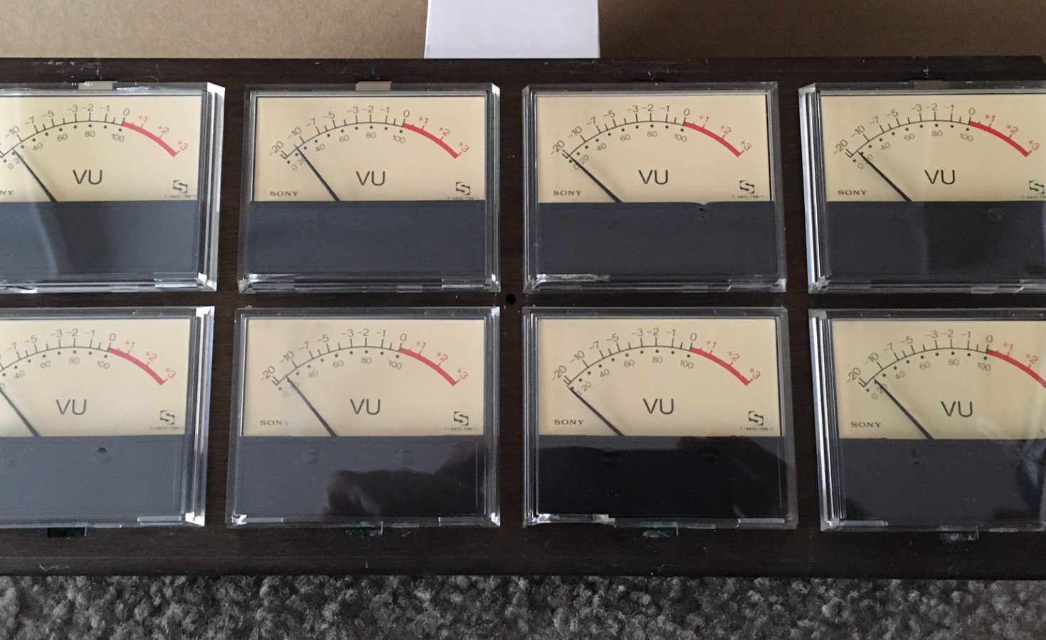
Here is a cluster of the analog meters removed from the meter bridge.
Here is a close up of the inside of the front part of the meter.
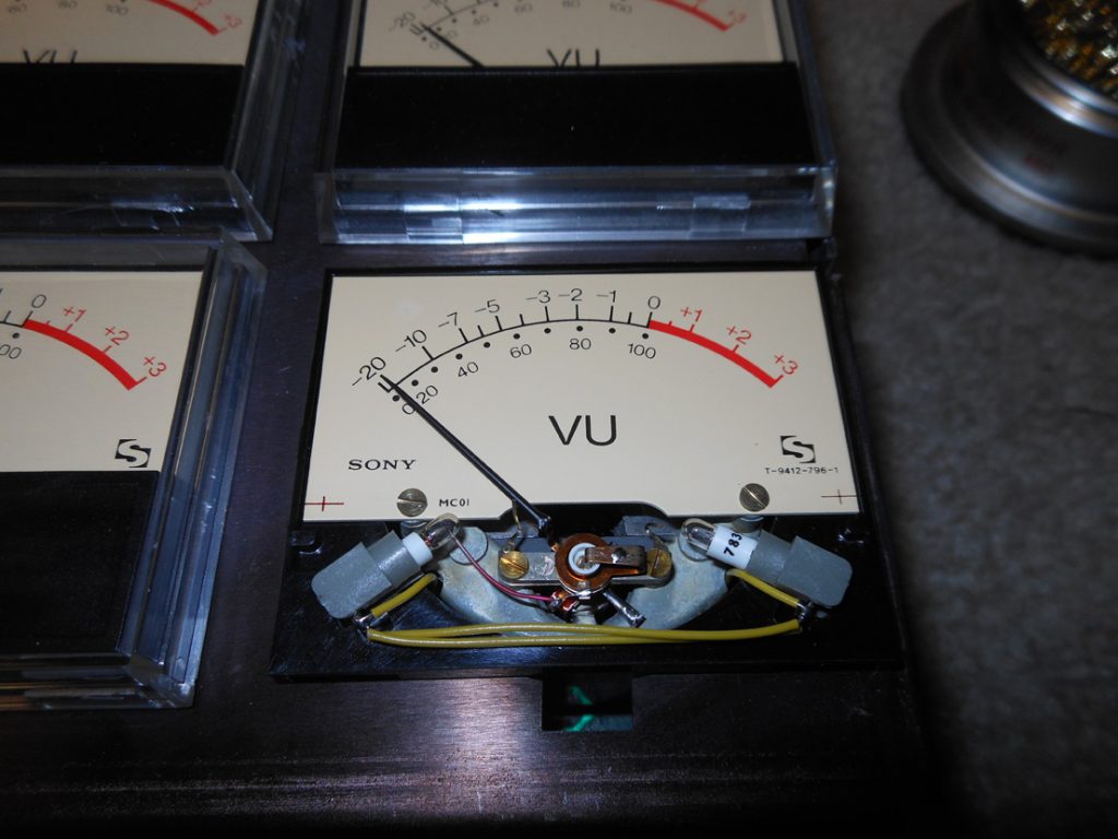
It just so happened that a 3mm led fits exactly into the lamp socket of the original incandescent lamp. Also in looking for yellow led’s I found some that were diffuse. Wonderful, perfect for this application.
The current wiring configuration is such that the lamps are wired in parallel. I need to wire the led’s in series as they are polarity sensitive. And fit a 1w resistor in there somehow. After a bit of different ways of putting all this together I came up with the following scenario.
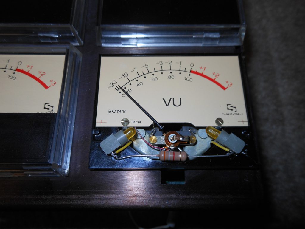
The + side of the voltage comes in thru the right led and passes thru the resistor through the left led to voltage -. This works very well other than if one of the led’s fail there is no light at all. A minor detail. Led’s last a very long time and generate pretty much no heat.
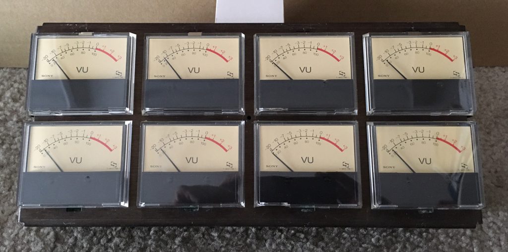
I did the first 8 meters and mounted them in the meter bridge and Shane was very excited. A very nice vintage look.
Here is an image of the 8 meters all lit up.

2005 HRD III
Got a email a few weeks ago from Lisa who was frustrated. Seems she bought a used Fender HRD (Hot Rod Deluxe) III off Reverb and it had developed some issues.
She had purchased it for her son to use and while it worked initially it was now exhibiting low headroom and snapping/crunching sounds.
They had taken it to several repair places around town and the techs pretty much said, “yeah, not a great amp. maybe new tubes will fix it”. Or they could not diagnose the problem.
Could I help her out.
Now, I don’t normally do repairs on newer amps but what the hell. They were in no particular rush as they had been dealing with the problem for many months.
So, I got the amp and a few days later put it on the bench and removed the chassis to get into the bowels of it.
I figured by the explanation of the problem it most likely was a tube or solder joint. But where?
First off touched up many solder joints in that made sense as to where there might be an issue and after that fired up the amp.
No issue! Huh! Tapped around the board expecting something aaaaand nothing. Oh well.
So, I let it cook for about half an hour playing audio through it at a moderate volume. Ok, lets do some more tapping on the board. Nada!
Alright, lets go on to the tubes. Starting with the power tubes nope, nope, PI nope, V2 OUCH!!!!
Ah hah! The V2 crunched madly. Replaced and we’re in business.
I did help them with improving the headroom issue by substituting the 12ax7’s in V1 and V2 with 12at7’s. Making the amp much more playable.
I did imply that a custom build from me would give the player a much better sounding & playing amp than the HRD series.
I go through all this explanation to point out that any competent tech can figure this issue out. It’s not rocket science.
All I can figure, is that the tech’s just are lazy. If they can’t fix it in 5 minutes forget it.
The point I want to make is support your boutique amp builder/servicer. They are willing to take the time and educate the player as to how their amp works and ways to improve the sound.
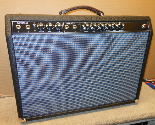
1965 Fender Style Deluxe Reverb
I usually do not build blackface style amps as there are many places you can find them.
However, a good friend of mine requested that I build one for him. With a few minor mods of course.
The deluxe is a medium power (22watts) amplifier. This one used a 12″ speaker of which I chose a Eminence Cannabis Rex.
The customer plays a semi-hollow guitar in the jazz idiom.
It was a pretty easy build with the exception of tracking down some defective components and poor solder connections.
Mods were as follows:
> put the bias adjustment on the outside. No need to pull the chassis when changing tubes.
> Up-graded some of the caps in critical signal circuits.
> Screened the top of the cabinet to prevent RF noise from entering the whole amp circuit.
Here are some pics:


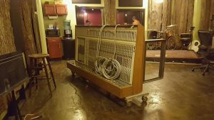
Howl Street Recording Updates Mixer
I assisted Shane at Howl Street Recording to install a wonderful Sony analog mixer to give his studio better mic-pres and analog sonic goodness.

A Power Tube Primer
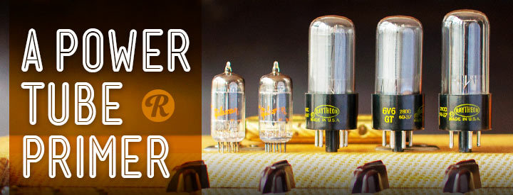
Check out this great article from REVERB.COM
Despite the complicated circuit diagrams found glued in their cabinets, tube amps are relatively simple creatures. They take an electrical signal, amplify it and turn it into sound via vibrating membranes (speakers). There are plenty of links in that chain that can affect your sound, but the biggest two are probably the type of speakers and the type of tubes being used. We’ll save speakers for another day and focus this article on the characteristic tones produced by four types of power tubes.
Let’s just get this out of the way: this is not a technical or historical article. These are just my opinions from playing a lot of amps with a lot of different tube types. I’ll try to describe here what I feel defines the response of each type of power tube in terms of tonality. The aim is to help you find the right amp for the tone you’re after without taking up too much of your time. This is how I hear it, but feel free to disagree in the comments thread. After all, difference of opinion and interpretation is part of what makes music great.

6V6 Tubes
Overall, this is my personal favorite type of tube, typically found in amps with less than 30 watts. Fender is well-known for using the 6V6, and you’ll find it most often where designers are chasing a low-powered “American” clean tone. What’s great about 6V6 amps is that they are very musical, especially for clean tones and distorted lead tones.
When playing lead, the tone feels more complex and really starts to sing. On the flip side, many players feel 6V6 amps are too loose for tight rhythm playing, especially with higher gain and lower frequencies. They can get a bit muddy when pushed and don’t track quick or intricate playing on the lower strings very well. The more you push a 6V6 amp, the more you’ll notice this undefined low end. Several amps equipped with 6V6s are renown for their clean tones, including the original Fender Deluxe Reverb, the original Fender Princeton and more recently the Fuchs Blackjack 21.

EL84 Tubes
The EL84 is a very chimey and tight beast. Also usually found in amps less than 30 watts, these are more common in British designs. The EL84 can bite when pushed, so in some amp designs they might feel stiff or harsh, but they can also hold distorted tones together better than a 6V6 amp. If you plan on playing higher gain or pushing the amp to its limits when playing rhythm, you may prefer an EL84 amp.
A friend of mine made me a Trainwreck clone that uses four EL84s and it sounds incredible. You’ll also find these in Vox AC15s and AC30s, as well as smaller Marshall amps like the current DSL combo series.

6L6 Tubes
The “other American tube.” These are found in most amps over 30 watts, though the power rating of the amp can vary quite a bit. 6L6 amps make a good canvas for preamps and pedals, so you’ll see a wide variety of 50 to 100-watt amps using these in the power section. From sparkly cleans to warm overdrive and modern high-gain tones, 6L6 amps can have a bigger low end without losing clarity. They also impart a bit of a mid-range scoop which many players appreciate.
I have a ‘64 Fender Tremolux with 6L6s that has the most gorgeous clean tones. This uncolored starting point seems to bring the best out of every pedal I run into it.

EL34 Tubes
Commonly referred to as the “British” sound, amps with EL34s in them are often assumed to have some sort of Marshall flavor. They are often viewed as the counterpart to the 6L6 and are usually found in amps over 30 watts. While not a one-trick-pony by any means (I have a Rivera with EL34s and it can do a pretty convincing Blackface), EL34 amps are generally assumed to have that Marshall mid-rangy bark. For that reason, EL34 amps are my favorite for distorted guitar tones of the classic rock variety. That Rivera is amazing, and my Marshall JMP is a 50-watt box of pure attitude.
It’s worth noting that tube choice is just one component of a larger overall design, so much of the tonal variance comes from the general circuit and not just the tubes themselves. As you play more and amps with different tubes, you’ll start to hear commonalities and see where these lines can be drawn. As for me, I’ve learned to appreciate the difference between each type as a great excuse to “need” a new amp…
Handmade Boutique Amps – FOR SALE –
If you’re searching for a quality Tweed style amp, contact me.
I would enjoy building any style for you.
Or, if you have a tweed, blonde, or blackface in need of repair or upgrading, let me know.