
Late 30’s National/Dobro amp
I was presented a old National amplifier by a client that had purchased it not working and wanted to get it up and going again. He thought it may be a model B version.
Upon inspection the main fuse was blown and there was a resistor that literally had exploded.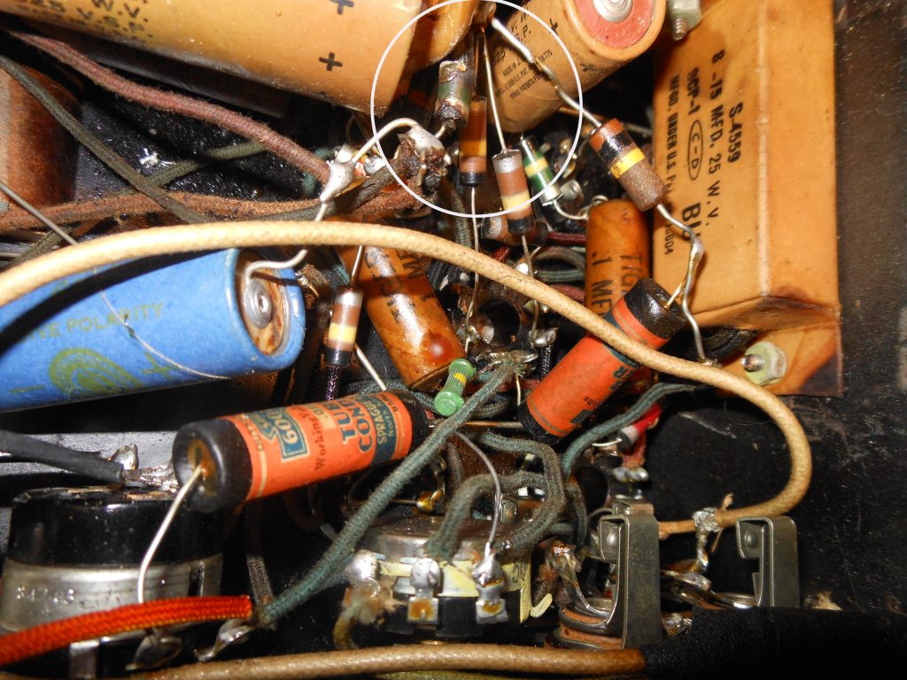
So, first up, what is it? After digging around the internet I discovered that this was actually a Model 13a-15. Made between 1937-38. Talk about ancient.
Finding out that it is a 13a-15 and comparing to what I had, I discovered that this unit was modified as well. Working on old products is a bit like detective work. Finding what it is and has there been any work done or added on to it. This particular model had lots of bits added to the circuits.
Whenever you dig into a piece that does not work you just need to start from the beginning. Why did the fuse blow? Why did the resistor explode?
> Is the power transformer good?
After disconnecting the main B+ from the rest of the circuit I slowly powered up the PT using a variac (variable ac power supply). No current draw. Excellent!
The PT is good.
> Is the rectifier tube good?
Tested the tube on a Hickok and all was good. Installed back into the circuit and powered up again using the variac. All was well.
> On to the rest of the power supply.
The filter caps looked old. Tested them and found all were defective. Not surprising as electrolytic caps do not last forever. Before I order replacements I needed to look at the rest of the amp including the exploded resistor.
One of the problems with that was, back at that time in electronics history, there was very little standards in resistor marking. More detective work.
If you look at the picture above you will notice that the resistors use a colored body with different bands of color. Not a whole lot on the net about these old markings. Dig dig and dig. I also metered the good resistors and coupled with the schematic and net info, I figured out the code.
> Tested more capacitors, and found defective ones.
> Tested the remaining tubes with the Hickok. All indicated good, no shorts.
> Traced out the mods and compared with the original schematic. Interesting! Just some added volume and a tone control. Cool, will leave as is.
> Ordered necessary parts.
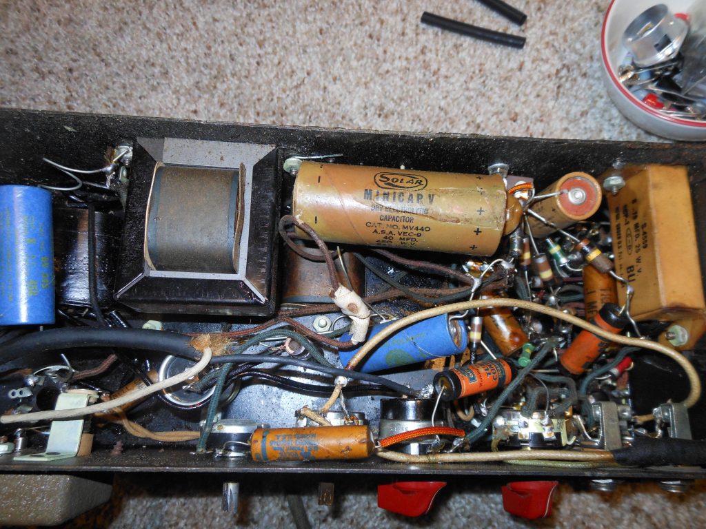
Kind of a mess. I am continually surprised at how some techs do their work. This was pretty hack!
So the resistor that had failed was a 5K ohm that fed the pre-amp and PI (phase inverter) circuit. That large brown cap as well as the blue and small brown cap were all defective. BTW that large cap was an add-on. Not part of the original circuit. Big question? Did the resistor fail causing the cap to go or did the cap fail causing the resistor to go.
So while waiting for the parts to show up I replaced the power cord with a 3 pin ground version and re-wired the ac power in. Safety first!
My thought moving forward is to remove parts that I know were not original to the schematic, rebuild the amp to original specs and take a listen.
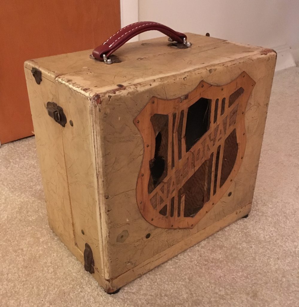
Also, the speaker part of the cabinet was falling apart. So off to see my good friend Kris who is a much better wood worker than I, to have him repair the cab. As you can see in the top photo it turned out great! I also added a replacement handle as after 70 years the original one was long gone.
Parts came in and were put in the proper locations. Powered up! Got sound and no unusual current draw. But a nice level of hum. Much more than there should be. Working on tracking down the hum I found 2 of the 6N7 pre-amp tubes to be micro-phonic and found some NOS ones on eBay.
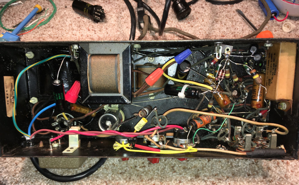
After several value changes and additions to the filter caps with no change in hum level, I studied the schematic closer and noticed that it indicated that the B+ going to the OT (output transformer) was connected on the input side of the choke. As a test, I wired it to the output side of the choke and the hum decreased at least 50% if not more. Cool! Much more acceptable.
I put the amp back together, took some pics and gave back to the client. His first impressions were great! He really liked the sound. After more playing he changed out the 6L6’s and found the amp to really come alive. The old ones were the RCA metal variety.
A week later the client indicated that he was a bit un-thrilled with the way the volume and tone controls worked as they took away good tone when adjusted under normal operations. Volume and tone controls should not dramatically alter the basic tone when being adjusted. So a slight re-design of the modded tone circuit and replacement of the main volume control was in order. Not wanting to really change the basic sound of this amp I looked at the various tone circuits that were used at that time in history. I settled on a tone circuit from a Gibson unit of that vintage.
So now, all is good and at the end of the day tone rules the guitar world.
