1959 Tweed Bassman – Part III
Part 3, More Assembly:
Next up is the high voltage filter capacitor board. This is a very important part, so make sure it is done correctly.
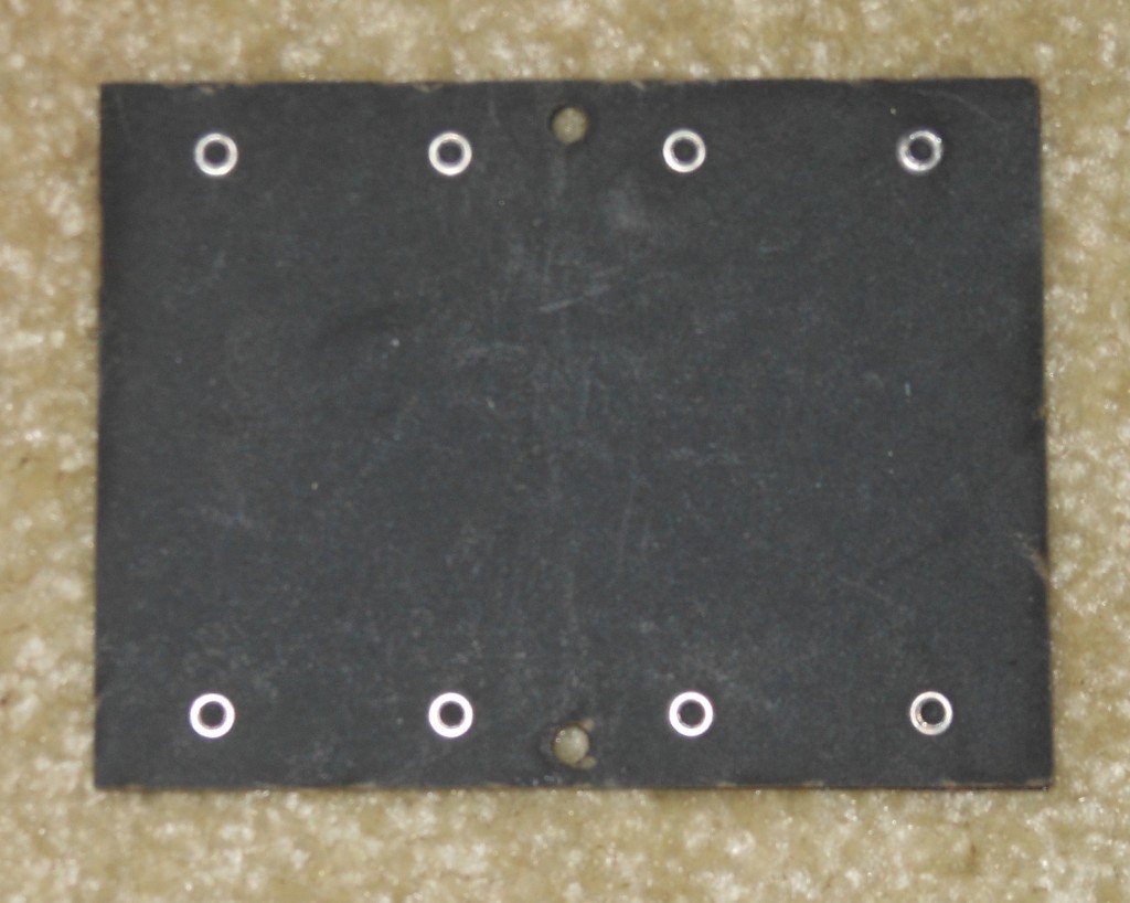 Notice position of the caps on the board and how the minus side of the caps are tied together.
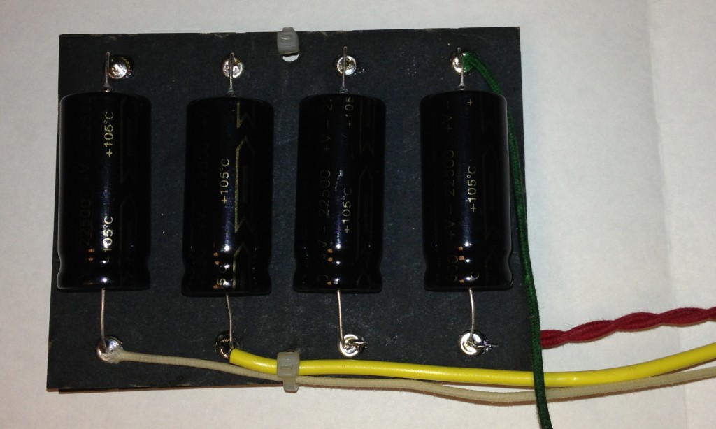
When done and wired go ahead and mount with “cover” to the chassis running the wires thru the grommet into the chassis. I did add some rubber feet to the bottom of the cap board to take up space under the cover so it does not bounce around and put some sticky pads on the chassis for the caps to sit on. Mount so that the caps sit on the chassis. 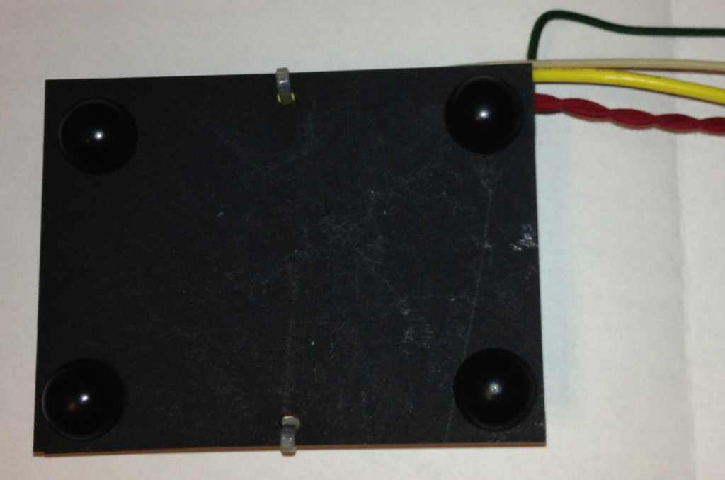
The main circuit board is pretty involved, so take your time. If you are a “righty” start on the left and work your way to the right. If a “lefty” reverse the procedure. Do the underside tie lines first before mounting components.
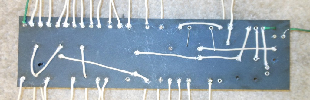 Double check you work constantly. I found myself making a few mistakes and corrected them by comparing the schematic to the wiring diagram. Pay particular attention to the 2 bias resistors (220k) and the 2 screen resistors (470). These need to match very closely in value in order to get the most out of your matched power tubes.
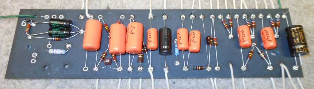 Wire all leads going from the board to the chassis components to the underside, as it will give a cleaner look. I also wrote the values of the orange drop caps on the caps to aid in servicing down the road. Dry fit the board to the chassis and drill 2 holes through both boards to mount directly to the chassis. Make sure you do not hit any wiring or components on the other side of the chassis.
Stay tuned for more to come on this exciting project!